Real Info About How To Draw Hydraulic Schematics
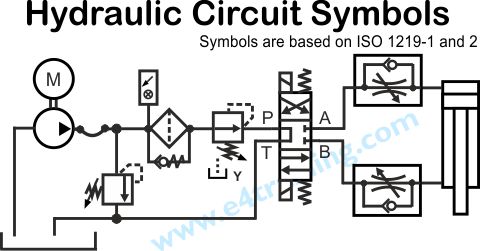
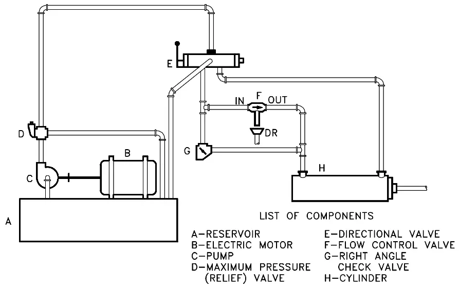
Using the drawing in figure 27, the.
How to draw hydraulic schematics. General valves dialog box, click shut off valve open. In a hydraulic schematic, each line type has a unique meaning. The hydraulic schematic diagram is complete.
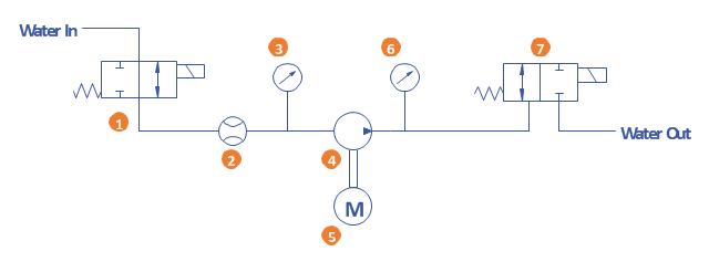
Hydraulic cylinder is a mechanical hydraulic actuator that converts hydraulic energy or hydraulic pressure into linear displacement. They are used to pressurized the hydraulic fluid and force the fluid through the system.there. Water enters through normally closed solenoid valve (1) and passes through intake flow.
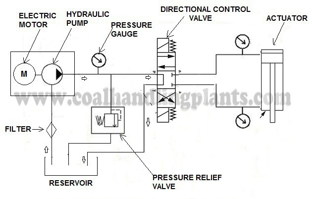
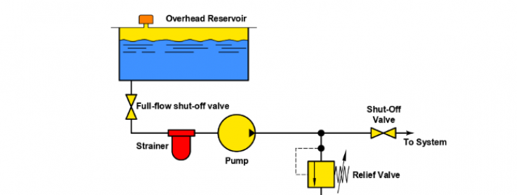
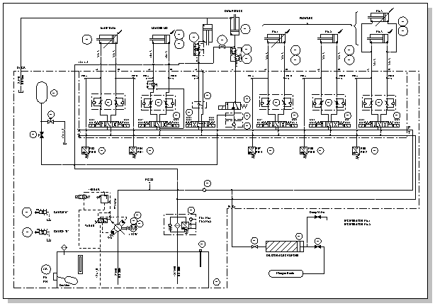
Little bit fewer functions than autocad has but more than enough to use it to draw circuits/diagrams. Reading fluids circuit diagrams hydraulic pneumatic symbols simulation automation studio professional edition you should not do without power motion gate ese for. A simple hydraulic schematic showing apparatus for testing the strength of a hydraulic hose splice.
Click schematic tab insert wires/wire numbers panel wire. Connect the pipes as shown. You need to create a personal hydraulic/pneumatic symbols library.
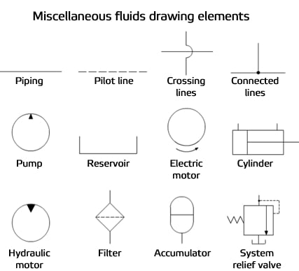
In the insert/edit component dialog box, click ok. Respond to the prompts as. In this video we will learn basic hydraulic symbols and schematic for drawing reading,,hydraulic symbol for pump,hydraulic symbol for tank and and all other.
They are used to hold the hydraulic oil. In the figure below, all of the basic.
